


CEAD
3D PRINTED TOOLING: 4 REAL-WORLD APPLICATIONS OF INDUSTRIAL 3D PRINTING FOR TOOLING
Original Source :
https://ceadgroup.com/resources/blog/4-applications-of-industrial-3d-printing-for-tooling/
Content Written by CEAD
While additive manufacturing is often described as a powerful technology to produce end-use parts directly, another one of its most transformative value lies in how it enables better tooling. In this context, tooling refers to all the specialized equipment manufacturers use to make other parts: from masters and plugs to molds, trim and drill fixtures, assembly jigs and handling aids.
These tools form the foundation of composite, metal-casting and concrete manufacturing and can be used at several stages in the manufacturing process. They let manufacturers shape, locate, trim and drill parts and thus are important to define geometry, ensure precision and make production reliable and repeatable.
Today, large format additive manufacturing (LFAM) is changing how these tools are made. Instead of stacking foam or machining large billets, manufacturers can 3D print near-net-shape patterns, molds and fixtures that require minimal finishing. The result: faster lead times, lower cost, lighter handling and a smaller materials footprint.
What is tooling?
In manufacturing fields such as composites, casting and concrete, tooling can appear at several stages of the process. Masters or plugs are used to define the shape of a mold, lay-up molds, concrete formwork, RTM molds and vacuum forming molds are examples of molds used to form end-parts, and fixtures and jigs support trimming, drilling, assembly or transport.
The composite toolchain usually contains the followings steps:
- A master or plug is created.
- The plug is used to create a mold.
- If the part requires trimming, a trim jig is produced.
- If necessary, a drill/assembly fixture is produced.
- For transportation, transport fixtures can be produced.
What markets and sectors use tooling?
The concept of tooling is used among various sectors. Everywhere where complex geometry or repeatable placement is required, tooling can optimize the production process.
Typical sectors where tooling is used include:
- Aerospace & aviation: fairings, interior panels, ducts
- Automotive & racing: RTM body panels, brackets, assemblies
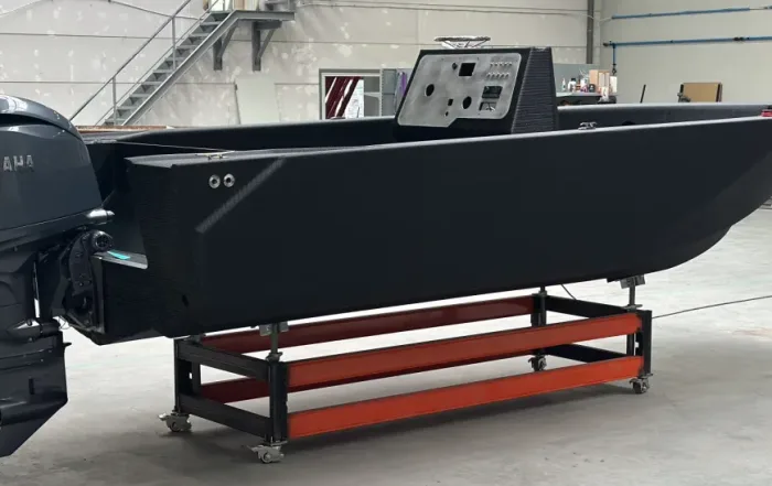
- Maritime: hulls, decks, nacelles, fairings
- Theme parks & architecture: scenic elements, complex concrete forms
- Construction: formwork, façade panels, bespoke cladding
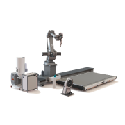
CNC milling on a Flexbot
Large format additive manufacturing of tooling
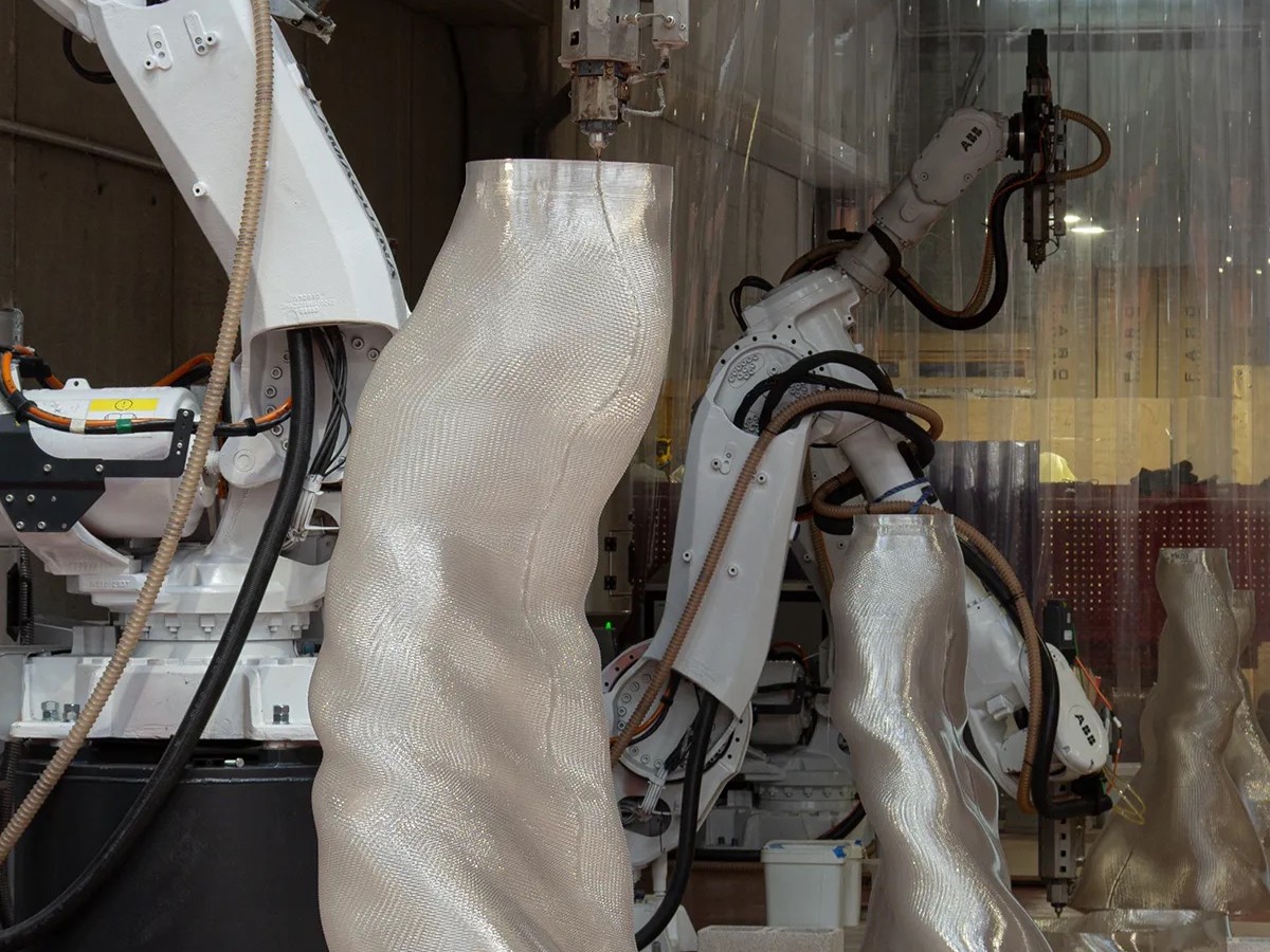
Different materials can be used for 3D printing tooling, including thermoplastics, composites, and metals. Each offers specific benefits depending on the application. Thermoplastic-based materials, however, are often the most efficient, cost-effective, and versatile choice for large-scale tooling. They provide an excellent balance between strength, machinability, and weight, while also being recyclable and easy to process.
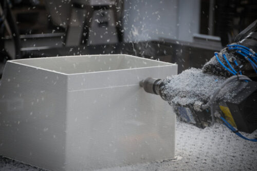
LFAM changes the speed at which tooling can be manufactured and used. Instead of laminating foam stacks or carving billets for weeks, you print to near-net-shape and machine only the functional surfaces that require tight tolerances.
The shift to using LFAM instead of traditional manufacturing methods, shortens schedules from months to weeks or even, reduces cost by cutting minimizing material removal and manual labor, and delivers lighter tools that are easier and safer to handle thanks to optimized designs by including shell-and-rib constructions to improve internal strength.
In addition to cost- and timing saving, additive manufacturing for molds and tooling offers important design advantages. Because the geometry is built layer by layer, functionality can be integrated directly into the design, such as stiffening ribs, vacuum channels, trim lines, datum pads and lift points. By combining design for additive manufacturing with subtractive manufacturing, post-processing steps are reduced: you CNC-mill only where accuracy matters.
Another advantage of LFAM can be found in the digital aspect of the technology. By storing tooling designs and data a digital inventory, the technology eliminates the need to warehouse physical tools for 30-40 years. When a LFAM-manufactured tool is no longer needed, you can simply shred it back to pellets and print the part again when needed.
3D Printed tooling: a case study
See how TMS produced a large composite trimming fixture with CEAD’s large-format additive manufacturing (LFAM) and hybrid finishing. The team moved from hand-built, labor-intensive tooling to a near-net-shape printed fixture finished by CNC, cutting lead time, reducing manual work, and simplifying handling on the shop floor.
Applications of 3D printed tooling
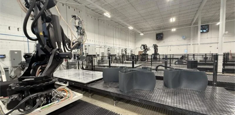
The cases below show LFAM tooling in practice: the Flexbot/Flexcube is used to print a near-net-shape, machine only where tolerances demand, and build in functions like vacuum channels and trim lines from the start.
Each example highlights a different objective: from trim & drill fixtures to hand lay-up molds. Each with measurable gains in lead time, cost, and handling. Use them as a reference for your own business case and click through for technical details per project.

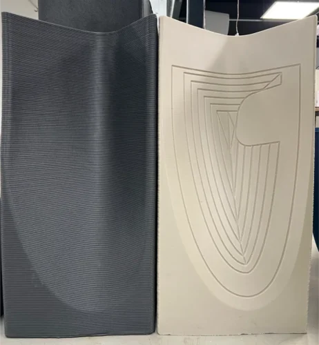
1. Trimming fixture
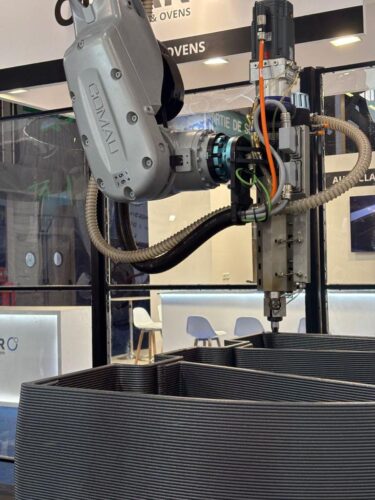
At JEC 2025 we live-printed a composite trimming fixture and demonstrated the full hybrid workflow. Toolpath strategy was prepared in Adaxis, deliberately showcasing start/stop transitions and bead control. The fixture printed in 14 hours, after which it moved straight to post-processing.
Finishing can be done on the very same machines that printed the tool: the Flexcube (gantry) or Flexbot (robot). We milled only the critical faces, with trim lines and vacuum channels already designed into the print. Watch CEAD application engineer Andrew explain the build and finishing steps in the video below.
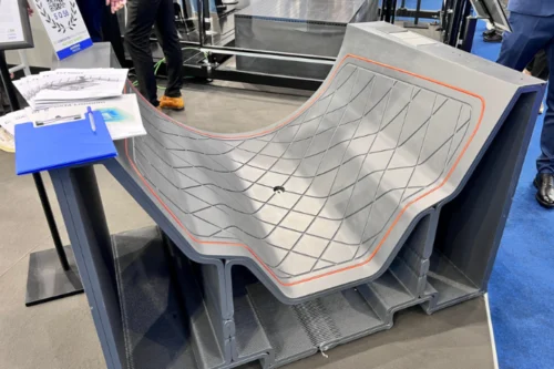
2. Trimming and drilling fixture
In partnership with AES, CEAD printed a composite trimming jig on the Flexbot and completed it with hybrid finishing. The build ran 15 hours to a near-net shape, followed by 6 hours of CNC-milling to surface datums and locator pads.
Airtech’s T-100GF material was used, a glass-fiber reinforced PET-G. This contributed to the stiff, machinable structure suited to repeat trimming cycles.
Designed for additive from the start, the fixture integrates vacuum channels, trim lines, and lift/handling features in the print. In production, a composite part is located on the jig and then robotically trimmed, delivering accurate, repeatable edges with minimal manual work.
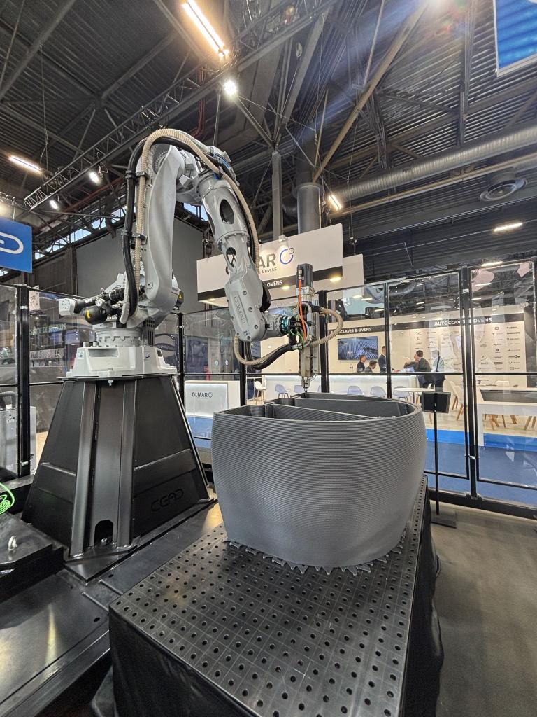
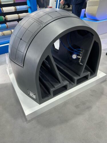
3. Hand lay-up silicone bagging
In collaboration with Fiberbus, CEAD produced a hand lay-up mold using the Flexbot and a hybrid print-then-mill workflow. The cell ran fully autonomously through the build, then transitioned to CNC for critical surfaces.
The whole process of printing and milling took about 20 hours. The material used was Polymaker’s glass-fiber reinforced PET-G, providing the stiffness, dimensional stability, and clean machinability required for repeated hand lay-up cycles.
4. Trimming tool for composite shell
Another interesting application of LFAM for a trimming fixture can be found in the UK. Total Machining Solutions (TMS) produced a composite trimming fixture using CEAD’s pellet extruder. The toolpath was prepared in Adaxis to balance bead width, start/stop management, and build speed, printing a near-net-shape fixture that moved straight into CNC for critical faces.
Because the fixture was designed for additive from the start, trim lines and vacuum channels were already integrated in the print, minimizing hand work and shortening the overall schedule.
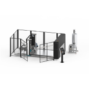
The Flexbot and Flexcube for 3D printed tooling
CEAD’s large format additive manufacturing solutions, the Flexbot (robot-based) and Flexcube (gantry-based), are built as modular, upgradable cells: start compact for development work, then scale build volume and throughput as programs grow. The architecture is hybrid by design—high-deposition, pellet-fed LFAM for speed, followed by integrated CNC finishing where tolerances and surface quality matter.
A CNC controller sits at the core, so machinists step into familiar workflows with precise, robust motion control. In multi-cell deployments the systems are fleet-aware, sharing jobs and data for a consistent process across shifts and sites, backed by global application support for onboarding and ongoing optimization.
The extrusion hardware is engineered for reinforced polymers: a nitrided barrel resists abrasion, enabling reliable processing of short-fiber thermoplastic composites. That opens a broad material window: from biobased blends (e.g., PLA or PP with cellulose fibers), through commodity staples (PP/ABS/ASA/PET/PC with glass fiber), up to high-end engineering grades (PEEK/PESU/PPS with carbon fiber) for demanding tools and fixtures.
Gantry vs robotic large scale 3D printing
The characteristics of gantry and robot-based LFAM solutions determine the specific advantages of these machines. From design freedom to increased accuracy, dive into the differences between gantry and robotic large scale 3D printing.
Start 3D printing tools
If you’re ready to shorten lead times and cut manual work, our team can help you scope, materialize, and deliver LFAM solutions tailored to your needs. Send our engineers a message and kickstart your additive manufacturing journey.